

Basic Structure of high Pressure Pipe Fittings and the Function of Each Part
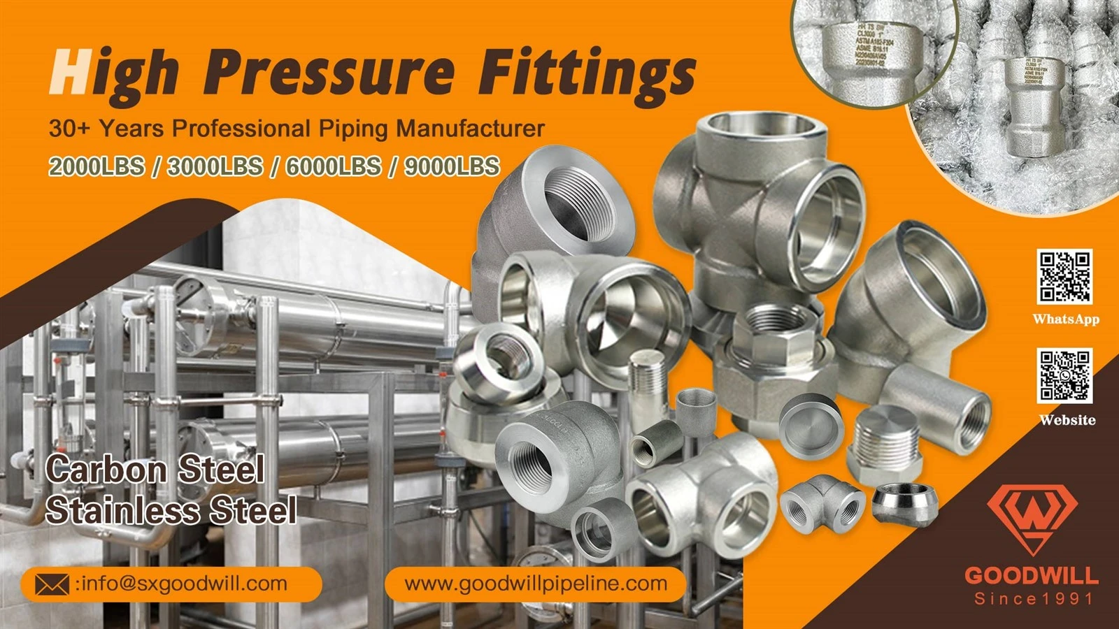 High pressure pipe fittings are critical components used to connect, redirect, branch, reduce, or terminate pipelines operating under elevated pressure conditions. They are widely used in oil and gas, petrochemical, chemical processing, hydraulic systems, power generation, mining, industrial manufacturing, and other demanding applications.
Unlike standard low-pressure fittings, high pressure pipe fittings must withstand significantly greater internal pressure, mechanical loads, temperature fluctuations, vibration, and pressure cycling. Their structural design therefore requires careful control of material strength, wall thickness, connection geometry, sealing surfaces, and manufacturing tolerances.
Common high pressure pipe fittings include elbows, tees, crosses, reducers, couplings, unions, nipples, plugs, caps, and specialized pressure-rated connectors.
Understanding the basic structure and function of each part helps purchasers, engineers, installers, inspectors, and distributors select suitable fittings and evaluate their quality more effectively.
1. Fitting Body
The fitting body is the main pressure-containing structure of a high pressure pipe fitting.
It provides the basic geometry of the fitting and carries the internal pressure generated by the working fluid.
Depending on the fitting type, the body may be:
Straight
Curved
Branched
Tapered
Closed
Multi-directional
The body must provide sufficient mechanical strength to resist:
Internal pressure
Tensile loads
Bending loads
Vibration
Thermal stresses
Pressure fluctuations
External mechanical forces
For high pressure applications, body geometry and material quality are particularly important.
2. Pressure Boundary
The pressure boundary consists of the portions of the fitting that contain the pressurized medium.
It includes the fitting body and, depending on the design, the connection and sealing structures.
The pressure boundary must prevent:
Leakage
Cracking
Rupture
Excessive deformation
Loss of structural integrity
Its design must consider the maximum working pressure, temperature, material strength, and applicable design standards.
3. Connection End
The connection end is the portion used to connect the fitting to a pipe, valve, equipment component, or another fitting.
High pressure fittings may use:
Threaded connections
Socket weld connections
Butt-weld connections
Flanged connections
Compression connections
Specialized high pressure connections
The connection type determines how mechanical loads and pressure forces are transferred through the piping system.
4. Threaded Section
Threaded high pressure fittings use precisely machined threads to establish a mechanical connection.
Common thread systems may include:
NPT
BSP
Metric threads
UNF or other specialized thread systems
The thread must have accurate:
Profile
Pitch
Diameter
Taper
Engagement length
High pressure applications require particularly careful thread control because thread defects can contribute to leakage or mechanical failure.
5. Thread Crest
The thread crest is the highest portion of the thread profile.
It contributes to correct engagement between mating male and female threads.
The crest must maintain appropriate dimensions and surface quality to prevent:
Poor engagement
Thread damage
Excessive installation resistance
Reduced connection strength
6. Thread Root
The thread root is the lowest portion of the thread profile.
It forms part of the structural cross-section of the threaded connection.
In high pressure fittings, thread-root geometry is particularly important because sharp or excessively deep machining features can create stress concentration.
Proper thread design helps balance sealing performance and mechanical strength.
7. Thread Flank
The thread flank is the angled surface between the crest and root.
It transfers mechanical forces between mating threads.
Accurate flank geometry contributes to:
Load transfer
Connection stability
Thread engagement
Sealing performance
Reduced wear
Poor flank machining can result in uneven loading and premature thread damage.
8. Sealing Surface
The sealing surface is the area responsible for preventing the pressurized medium from escaping through the connection.
Depending on the fitting design, sealing may occur through:
Thread interference
O-rings
Metal-to-metal contact
Gaskets
Ferrules
Specialized sealing elements
The sealing surface must be accurately manufactured and protected against scratches, dents, contamination, and deformation.
9. O-Ring
Some high pressure fittings use O-rings as primary or secondary sealing elements.
The O-ring is installed in a precisely machined groove and compressed during assembly.
Its function is to block the passage of fluid through the connection.
Common O-ring materials include:
Nitrile rubber
Fluorocarbon rubber
EPDM
PTFE-based materials
Other application-specific sealing compounds
Material selection must consider pressure, temperature, and fluid compatibility.
10. Backup Ring
A backup ring may be installed alongside an O-ring in high pressure applications.
Its primary function is to prevent the O-ring from being forced into the clearance gap under high pressure.
A backup ring can improve:
Extrusion resistance
Seal stability
High pressure performance
O-ring service life
The backup ring material and dimensions must be compatible with the specific sealing system.
11. Metal-to-Metal Sealing Surface
Some high pressure fittings use metal-to-metal sealing instead of elastomeric seals.
Precisely machined metallic surfaces come into contact under controlled assembly force to create the seal.
This design can provide advantages in applications involving:
Very high pressure
High temperature
Aggressive fluids
Long-term service
The surface finish and dimensional accuracy of the mating surfaces are critical.
12. Gasket
Some high pressure connections use a gasket between mating surfaces.
The gasket fills microscopic surface irregularities and creates a pressure-resistant sealing barrier.
Depending on the application, gasket materials may include:
Metal
Graphite
PTFE
Spiral-wound materials
Other specialized materials
The gasket must be compatible with the pressure, temperature, and fluid.
13. Wall Thickness
Wall thickness is a major structural parameter of high pressure fittings.
Adequate thickness provides resistance against internal pressure and external mechanical loads.
Required wall thickness depends on:
Fitting size
Working pressure
Material grade
Operating temperature
Design standard
Service conditions
Wall thickness must be sufficiently uniform to avoid local weak points.
14. Reinforced Section
Some high pressure fittings include reinforced sections around connection areas, branches, or transitions.
Reinforcement provides additional material where stresses may be concentrated.
It can improve resistance to:
Pressure
Bending
Fatigue
Local deformation
The reinforcement geometry must be carefully designed to avoid creating new stress concentrations.
15. Branch Section
In tees and crosses, the branch section creates an additional flow path.
The branch must withstand both internal pressure and mechanical loads generated by connected piping.
The transition between the branch and main body is especially important because this area can experience concentrated stresses.
16. Branch Outlet
The branch outlet is the connection end of the branch.
It may use:
Threaded connection
Socket weld
Butt weld
Flanged connection
Specialized connection
Its dimensions must correspond to the connected pipe or equipment.
17. Elbow Bend
In high pressure elbows, the bend redirects the pipeline.
The bend must maintain appropriate wall thickness and geometric accuracy throughout the curved section.
Poor forming may cause:
Excessive wall thinning
Wrinkling
Ovality
Local stress concentration
These defects can be particularly serious in high pressure systems.
18. Elbow Radius
The elbow radius determines how sharply the direction of flow changes.
Common configurations include:
Long-radius elbows
Short-radius elbows
Special-radius elbows
The radius affects:
Flow resistance
Pressure loss
Stress distribution
Installation space
Pipeline geometry
For high pressure systems, radius selection should be based on both hydraulic and mechanical requirements.
19. Reducer Transition
Reducers connect pipes of different diameters.
The transition between the large and small ends must be gradual enough to maintain appropriate structural strength and flow characteristics.
Two common configurations are:
Concentric reducers
Eccentric reducers
The appropriate design depends on the piping arrangement and process requirements.
20. Coupling Section
A coupling connects two pipes or components, usually along the same axis.
Its body must provide sufficient strength around both connection ends.
For threaded high pressure couplings, the internal thread length and wall thickness around the threads are particularly important.
21. Nipple Section
A nipple is a short length of pipe with connection threads or other end configurations.
High pressure nipples may be used to:
Extend piping
Connect fittings
Connect valves
Adapt equipment
Create compact piping arrangements
The nipple wall thickness and thread engagement must be appropriate for the intended pressure rating.
22. Socket
Socket-type high pressure fittings contain an internal socket designed to receive the pipe.
The socket provides controlled positioning before welding.
Its dimensions influence:
Pipe insertion
Welding preparation
Alignment
Joint strength
The socket must be manufactured accurately to maintain consistent assembly quality.
23. Socket Weld Area
The socket weld area is the external region where the pipe is welded to the fitting.
The welding area must have sufficient material thickness to withstand welding heat and operating loads.
Welding procedures must be compatible with the fitting material and application.
24. Butt-Welding End
Some high pressure fittings use butt-welding ends.
The end is prepared for direct welding to a pipe or another fitting.
Important parameters include:
Outside diameter
Wall thickness
Bevel angle
Root face
End roundness
Accurate end preparation is essential for achieving reliable welded joints.
25. Bore
The bore is the internal opening through which the fluid passes.
Its dimensions influence:
Flow area
Pressure loss
Velocity
Turbulence
Overall system efficiency
The bore should be manufactured consistently and remain free from harmful defects.
26. Internal Flow Passage
The internal passage connects the inlet and outlet portions of the fitting.
Its geometry depends on the fitting type.
For example:
Elbows change flow direction.
Tees create branches.
Reducers change diameter.
Couplings maintain a straight connection.
A well-designed internal passage can reduce unnecessary pressure loss and turbulence.
27. Wrenching Surface
Many high pressure threaded fittings include a hexagonal or other wrenching surface.
This surface allows installers to apply controlled torque during assembly.
A sufficiently strong wrenching section helps prevent:
Body deformation
Thread damage
Installation difficulties
The wrenching surface should be designed for the required installation torque.
28. Shoulder
A shoulder may be incorporated into the fitting body to provide a defined transition or mechanical stop.
Depending on the design, it can:
Control assembly depth
Support mating components
Transfer mechanical loads
Protect sealing elements
The shoulder geometry must be accurately controlled.
29. Stop Surface
A stop surface limits the insertion or movement of a mating component.
It helps ensure that components reach the correct assembly position.
This is particularly important for specialized compression, socket, and mechanical connection systems.
30. Material Structure
High pressure fittings are manufactured from materials capable of handling demanding mechanical and environmental conditions.
Common materials include:
Carbon steel
Stainless steel
Alloy steel
Duplex stainless steel
Nickel alloys
Other high-performance materials
Material selection depends on:
Pressure
Temperature
Fluid
Corrosion conditions
Required mechanical strength
Applicable standards
31. Heat Treatment
Heat treatment may be used to obtain the required mechanical properties and microstructure.
Depending on the material and manufacturing process, treatments may include:
Normalizing
Annealing
Quenching and tempering
Solution treatment
Other specified treatments
Proper heat treatment can influence:
Strength
Toughness
Hardness
Ductility
Fatigue performance
For critical high pressure fittings, heat treatment records may form part of the required quality documentation.
32. Surface Treatment
Surface treatment may be applied to improve corrosion resistance and durability.
Depending on the material and application, treatments may include:
Zinc plating
Nickel plating
Phosphate treatment
Black oxide
Anti-corrosion coating
Passivation
Specialized protective coatings
The treatment should be compatible with the service environment.
33. Identification Marking
High pressure fittings normally require clear identification and traceability.
Markings may include:
Manufacturer
Material grade
Size
Pressure rating
Standard
Heat number
Product code
Clear markings help buyers and inspectors verify product identity and traceability.
34. How the Main Components Work Together
The main structural relationship of a high pressure pipe fitting can be summarized as:
Fitting body → contains internal pressure and provides structural strength
Wall thickness → provides pressure resistance
Connection end → connects the fitting to the piping system
Threads or weld ends → create the mechanical connection
Sealing surface → prevents leakage
O-ring or gasket → provides additional sealing
Backup ring → prevents seal extrusion under high pressure
Bore → maintains the internal flow passage
Branch section → creates additional flow paths
Elbow radius → controls directional change
Reducer transition → changes pipe diameter
Wrenching surface → facilitates controlled installation
Material and heat treatment → determine mechanical performance
Together, these components allow high pressure fittings to maintain structural integrity and reliable sealing under demanding operating conditions.
35. How High Pressure Fittings Handle Pressure
When pressurized fluid enters the piping system, internal pressure acts against the fitting's internal surfaces.
The fitting body and wall structure resist this pressure.
At the connection, the mechanical connection and sealing components prevent the fluid from escaping.
The load is distributed through:
Internal pressure → fitting body → connection structure → connected pipe
At the same time:
Assembly force → sealing element → sealing surface → pressure barrier
The design must ensure that these forces remain within acceptable limits under both normal operation and pressure fluctuations.
36. Why Structural Understanding Matters for Procurement
High pressure fittings should not be evaluated based solely on appearance or unit price.
Structural details can directly influence service reliability.
For example:
Insufficient wall thickness can reduce pressure resistance.
Poor thread geometry can cause leakage or connection failure.
Inaccurate sealing surfaces can cause persistent leakage.
Poor elbow forming can create local thinning.
Weak branch transitions can increase stress concentration.
Incorrect material selection can lead to corrosion or mechanical failure.
Inconsistent heat treatment can affect strength and toughness.
Understanding these components allows purchasers to make more informed supplier comparisons.
37. Key Quality Inspection Points
When purchasing high pressure pipe fittings, buyers should pay particular attention to:
Material
Verify material grade, chemical composition, and relevant material certificates.
Dimensions
Check:
Outside diameter
Inside diameter
Wall thickness
Overall length
Thread dimensions
Connection dimensions
Threads
Inspect:
Thread profile
Pitch
Diameter
Engagement
Surface condition
Welding Ends
For welded fittings, check:
Bevel
Root face
Diameter
Roundness
Surface condition
Sealing Components
Verify:
Material
Dimensions
Hardness where applicable
Pressure compatibility
Chemical compatibility
Body
Inspect for:
Cracks
Laminations
Forging defects
Casting defects
Excessive deformation
Surface damage
Heat Treatment
Confirm the required heat treatment condition and documentation.
Pressure Testing
Where required, perform or verify appropriate pressure and leakage testing.
Non-Destructive Testing
Depending on the application and specification, testing may include:
Ultrasonic testing
Magnetic particle testing
Liquid penetrant testing
Radiographic testing
Other specified examinations
38. Basic Procurement Checklist
Before purchasing high pressure pipe fittings, buyers should confirm:
| Item | What to Check |
|---|---|
| Fitting Type | Elbow, tee, reducer, coupling, nipple, cross, etc. |
| Material | Carbon steel, stainless steel, alloy steel, etc. |
| Size | Nominal pipe size |
| Pressure Rating | Required working pressure |
| Temperature | Operating temperature |
| Connection | Threaded, socket weld, butt weld, flange, etc. |
| Thread | NPT, BSP, metric, or specified standard |
| Wall Thickness | Required pressure-bearing thickness |
| Sealing | O-ring, gasket, metal-to-metal, or other |
| Bore | Internal flow dimensions |
| Geometry | Radius, branch, reducer transition, etc. |
| Heat Treatment | Required treatment condition |
| Surface | Machining and surface quality |
| Corrosion Protection | Required surface treatment |
| Testing | Pressure, leakage, dimensional, and NDT requirements |
| Certification | Material and product documentation |
| Marking | Identification and traceability |
| Packaging | Protection against impact and contamination |
| Supplier | Manufacturing capacity and quality-control capability |
39. Conclusion
High pressure pipe fittings are engineered pressure-containing components whose reliability depends on the coordinated performance of multiple structural elements.
The fitting body and wall thickness provide the primary pressure resistance, while the connection ends, threads, welding areas, and mechanical structures establish the connection with the piping system. The sealing surfaces, O-rings, gaskets, and backup rings prevent leakage, while the bore and internal flow passage maintain the required fluid path.
Other components, including the elbow radius, branch section, reducer transition, socket, wrenching surface, shoulder, and stop surface, provide specialized mechanical or installation functions.
For buyers, engineers, and distributors, the most important procurement considerations include material grade, pressure rating, wall thickness, connection type, dimensional accuracy, sealing design, heat treatment, surface quality, corrosion resistance, pressure testing, non-destructive testing, certification, traceability, and supplier manufacturing capability.
A high-quality high pressure fitting should not only meet dimensional requirements but also maintain reliable mechanical strength and sealing performance throughout its intended service life. Selecting fittings according to the actual pressure, temperature, fluid, connection method, and applicable industry standards is therefore essential for building a safe and dependable high pressure piping system.